


Saito FG-60R3
 03-05-2019, 04:02 PM
#2126
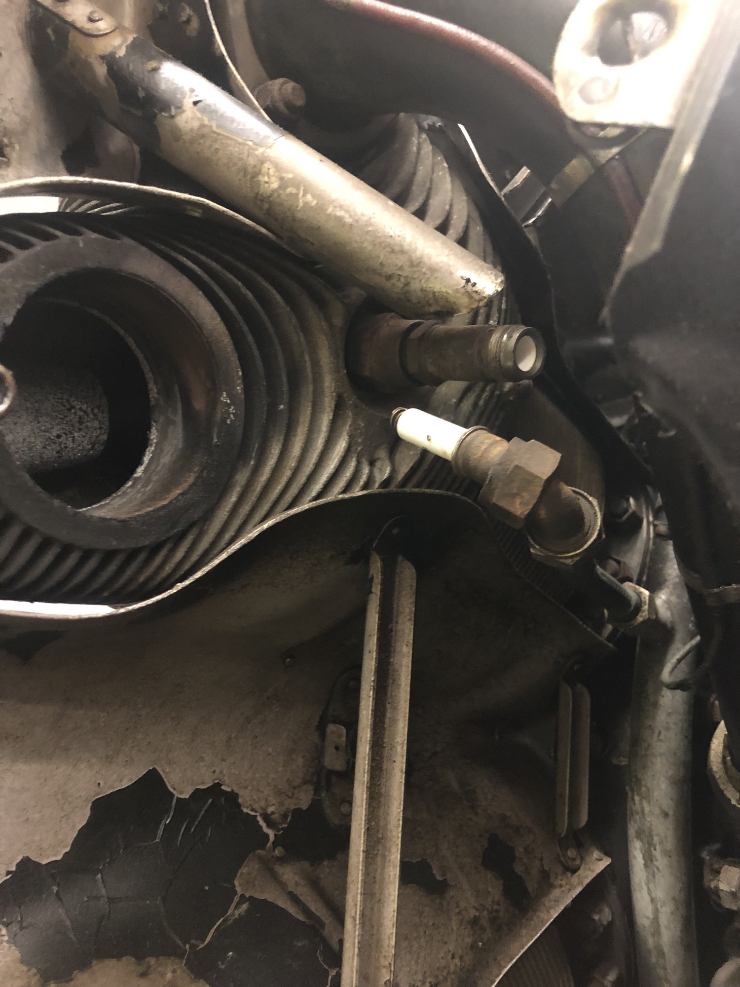
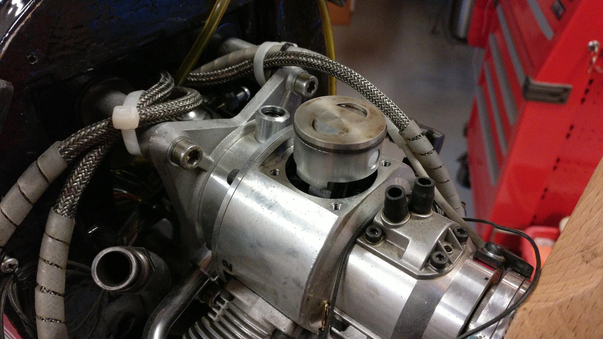
This is the back side of the engine.
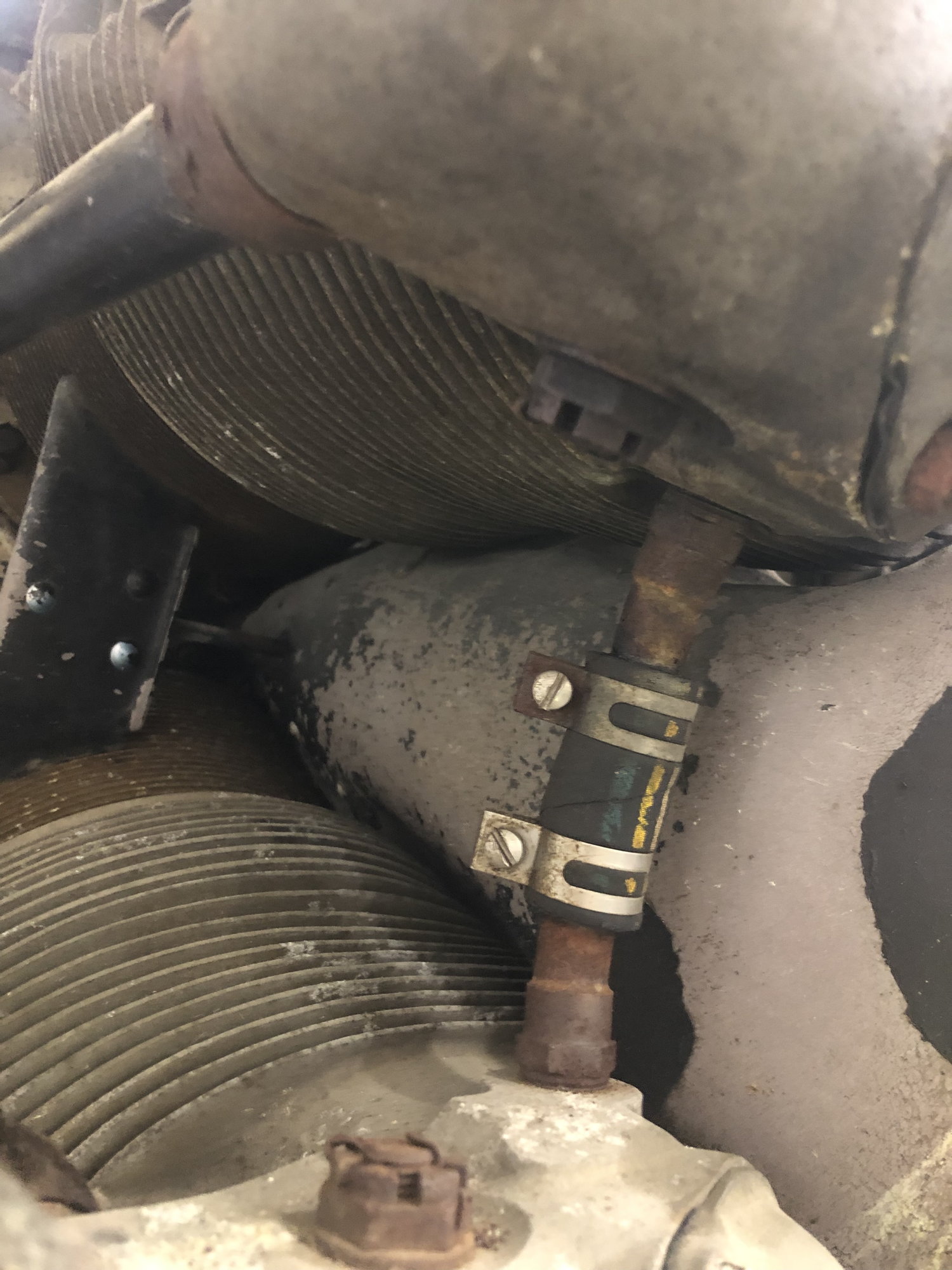
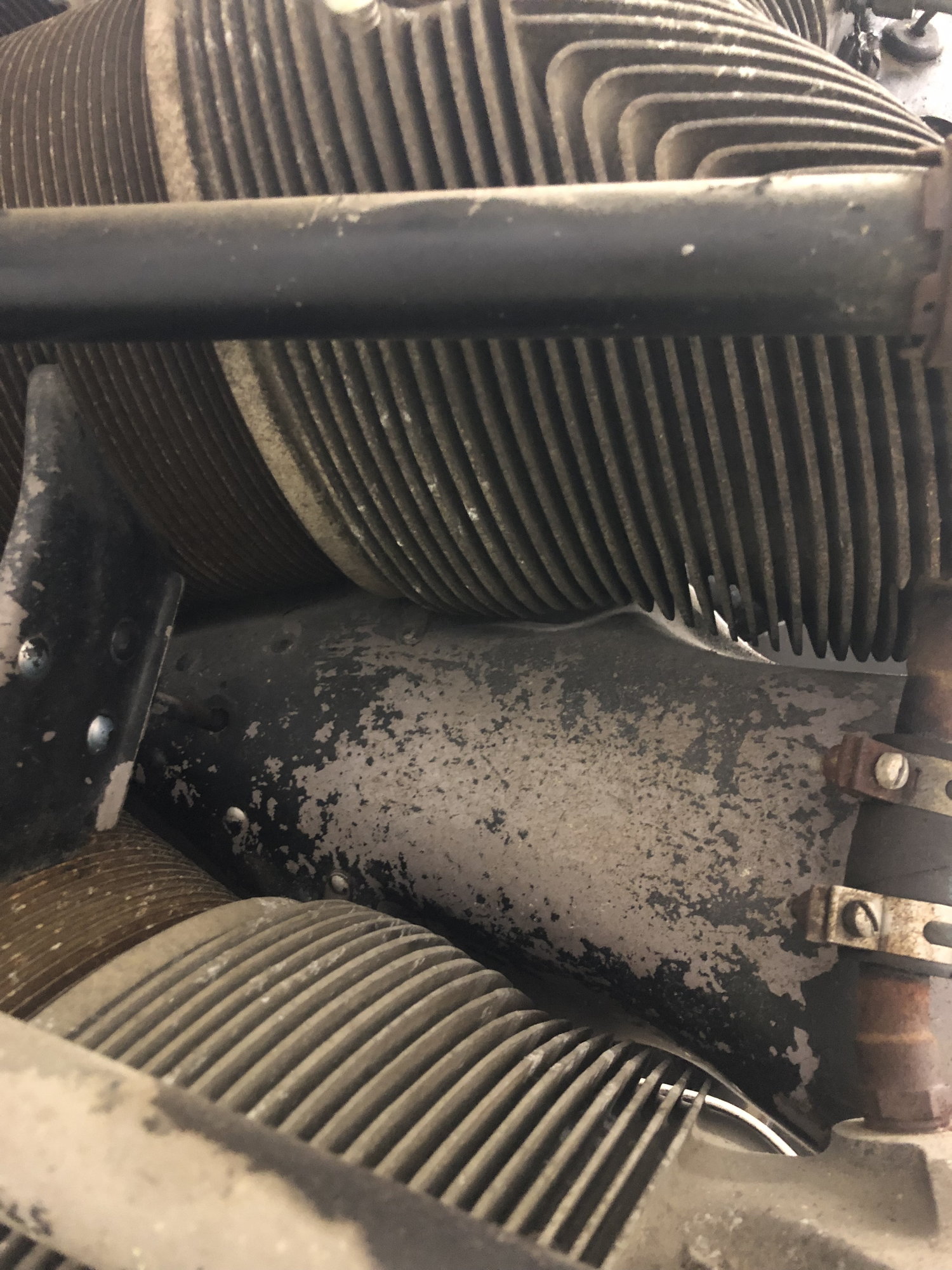
Went to my local EAA chapter 162 meeting. One of the members purchased a Canadian built Harvard and is restoring it. He invited us out to see the project so I took some pictures of his engine and baffling. Here is what I got!
 03-19-2019, 10:55 PM
#2127
Member
Some news...in fact a new issue.
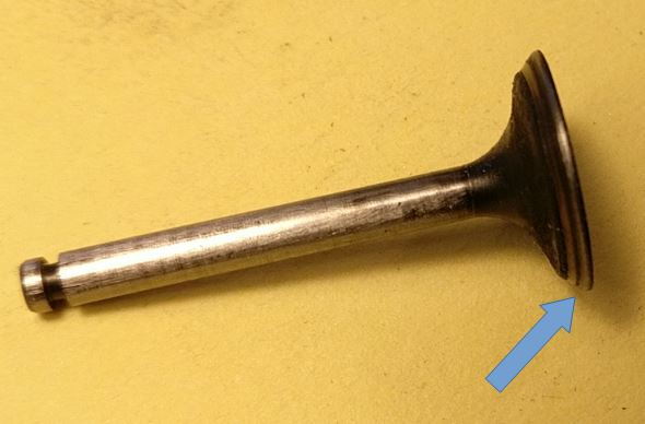
#1 cylinder exhaust valve was seized in its guide. After dismantling, I was surprised by the groove (blue arrow) on the valve seat. No other visible damage.
The engine has already been reassembled.
This engine has about 30 hours of operation and is 4 year old
JM
#1 cylinder exhaust valve was seized in its guide. After dismantling, I was surprised by the groove (blue arrow) on the valve seat. No other visible damage.
The engine has already been reassembled.
This engine has about 30 hours of operation and is 4 year old
JM
03-20-2019, 05:01 AM
#2128

Join Date: Jan 2007
Location: Dubai, UNITED ARAB EMIRATES
Posts: 500
Likes: 0
Received 2 Likes
on
2 Posts
JieM,
Was there a lot of carbon build up on the valve stem? You saw in the picture of mine after the cylinder failure, the exhaust valves in particular had a LOT of carbon on them. Mine also had that groove, although it was not as pronounced as yours. I have waited about 45 days for valves to come into stock, although that was with my supplier, they may be available somewhere else.
I am doing the intake conversion to negative crank pressure, and then I am going to run it on 30:1 ratio as it wont need as much oil going past the rings into the crank, I am hoping this will reduce the amount of carbon build up. I may also consider moving to Stihl oil instead of redline, as some at my field have reported less carbon build up on their engines (not all Saito engines).
Not saying anyone should follow my lead, but I am doing some experimenting.
These engines are not built to last a lifetime like some others are.
03-20-2019, 11:26 PM
#2129
Member
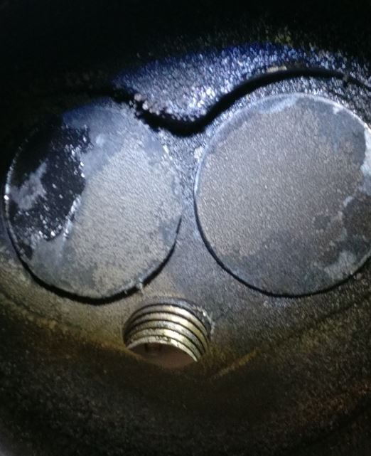
Carhurga, I was surprised by the low amount of carbon on the valve stem (no picture but +0.1mm on the diameter under the heat) and in the combustion chamber. see picture.
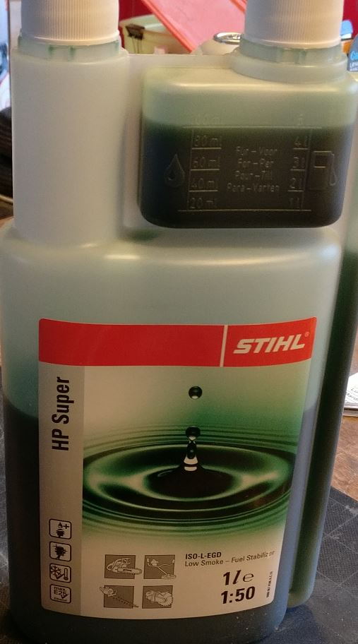
I run with a 25:1 ratio with Stihl HP super oil and SP98 E5 gas (5% ethanol max, we have no more ethanol free gas in France).
On my side I am also doing some experiments, and that's why I use a 9kg Beaver. It is easier to land after a engine trouble as a 14kg warbird...
Of course no one is obliged to follow my trials, but it's interesting to share experiences.
JM
03-21-2019, 01:23 AM
#2130
Join Date: Jan 2007
Location: Dubai, UNITED ARAB EMIRATES
Posts: 500
Likes: 0
Received 2 Likes
on
2 Posts
For an engine as old as yours, with as much run time, that is a hell of a lot less carbon than mine! Since you have also changed yours to a negative pressure crankcase, have you considered changing to a higher ratio? I have seen some people (cant remember who) that are running 30:1, so thats where I am going to start. I wanted to try and get the Stihl HP Ultra, but there isnt anyone who stocks it in the UAE, so will have to go with the plain old HP.
My parts should be arriving soon, so hopefully I can get this crate running again soon, and will probably fly it on a 3D plane, for the same reasons you are....if it quits, I can get it back....
I really dont know how long parts for the FG60 are going to be available, but I think this engine will be disco'd in the not too distant future. Just getting valves was a problem. If they are wearing like yours and mine, then putting new valves in, would most likely need new cylinders as well, as the seats will be worn too. Basically a new engine...
I am going to get a UMS 90cc 7-cyl radial next. It is the same diameter as the FG60, with possibly a bit more power. The best thing about the UMS, is that the cylinder head is seperate from the cylinder, so maintenance is possible on each cylinder without having to remove back plates etc, you can even replace/maintain in the plane.
Better or worse than the Saito, time will tell..
03-22-2019, 08:23 AM
#2131
Member
After my intake modification i have used a 33:1 ratio without any visible issue. But as this engine runs on bronze bushing and not on needle bushing, I prefer to come back to 25:1 (Stihl HP ratio recomendation for a 2 stroke engine X 2)
Note 1: I have removed the cylinder without removing the engine from the plane. It works with the Saito exhaust pipes, but not with the Keleo ring.
Note 2: I have bought a FG61TS and I hope that I will have less fears to put it in a Ziroli AT6...
JM
Note 1: I have removed the cylinder without removing the engine from the plane. It works with the Saito exhaust pipes, but not with the Keleo ring.
Note 2: I have bought a FG61TS and I hope that I will have less fears to put it in a Ziroli AT6...
JM
03-22-2019, 07:56 PM
#2133
My Feedback: (6)
Av Gas will have no impact on the build up of carbon. I assume you are considering running 100LL avgas there are many kinds but that is the most prevalent type of fuel.
Lower octane would be better 80/87 ava gas. Higher octane fuel burns faster. Stay with regular pump gas if you can find it with out any Alcohol that is better you can search the internet for availability near you.
Sparky
Lower octane would be better 80/87 ava gas. Higher octane fuel burns faster. Stay with regular pump gas if you can find it with out any Alcohol that is better you can search the internet for availability near you.
Sparky
03-22-2019, 08:09 PM
#2134

My Feedback: (43)
The thought of using avgas has nothing to do with carbon, it has everything with letting the lead cushion and lubricate the impact of the valve to the seat to perhaps lessen the valve wear shown above. This is why cars had to go to hardened valve seats in the early-mid 70s.
Last edited by JeffH; 03-22-2019 at 08:13 PM.
03-23-2019, 08:06 AM
#2135
Senior Member

Av Gas will have no impact on the build up of carbon. I assume you are considering running 100LL avgas there are many kinds but that is the most prevalent type of fuel.
Lower octane would be better 80/87 ava gas. Higher octane fuel burns faster. Stay with regular pump gas if you can find it with out any Alcohol that is better you can search the internet for availability near you.
Sparky
Lower octane would be better 80/87 ava gas. Higher octane fuel burns faster. Stay with regular pump gas if you can find it with out any Alcohol that is better you can search the internet for availability near you.
Sparky
I have found just the opposite with my modified 500 HP N/A Gen 3 5.7 Hemi. 110 octane racing fuel reduced low end TQ and killed my 60' times compared to 93 octane unleaded pump gas with 10% ethanol.
Unless the engine requires higher octane due to spark advance and/or compression ratio, higher octane can not increase power output. In fact it is far more likely to reduce power.
Last edited by SrTelemaster150; 03-23-2019 at 08:10 AM.
03-23-2019, 06:19 PM
#2137
Got my P-47 out today. I got 4 flights in on the Fg-60. First flight went great except for the landing. We had a dead cross wind and even with chopping to throttle down to idle I kept over shooting the runway. I ended up cutting the ignition unfortunately it ballooned real hard as soon as I did and slammed on the runway. No damage thank goodness.
Two things i noticed in this flight. The plane was �slicker� today and I only needed 1/2 throttle. I was really trying to keep the rpm down and not over rev it. Every time I looked at my telemetry read out the temps were around 270 ish or cooler. The engine was on point today. So I will say that I did change my oil mix. I changed it from Stihl Ultra HP to Redline racing oil. I got it from my motorcycle dealer here in town. I didn�t retune the motor on the low side but I did richen up the high speed two clicks. Also I did have to lower my idle trim a good bit so it wouldn�t roll by itself. All in all I had a great day of flying the 60R3. Here is a pic of my telemetry after a flight. Again I was lowering throttle in dives and not going over 75% throttle.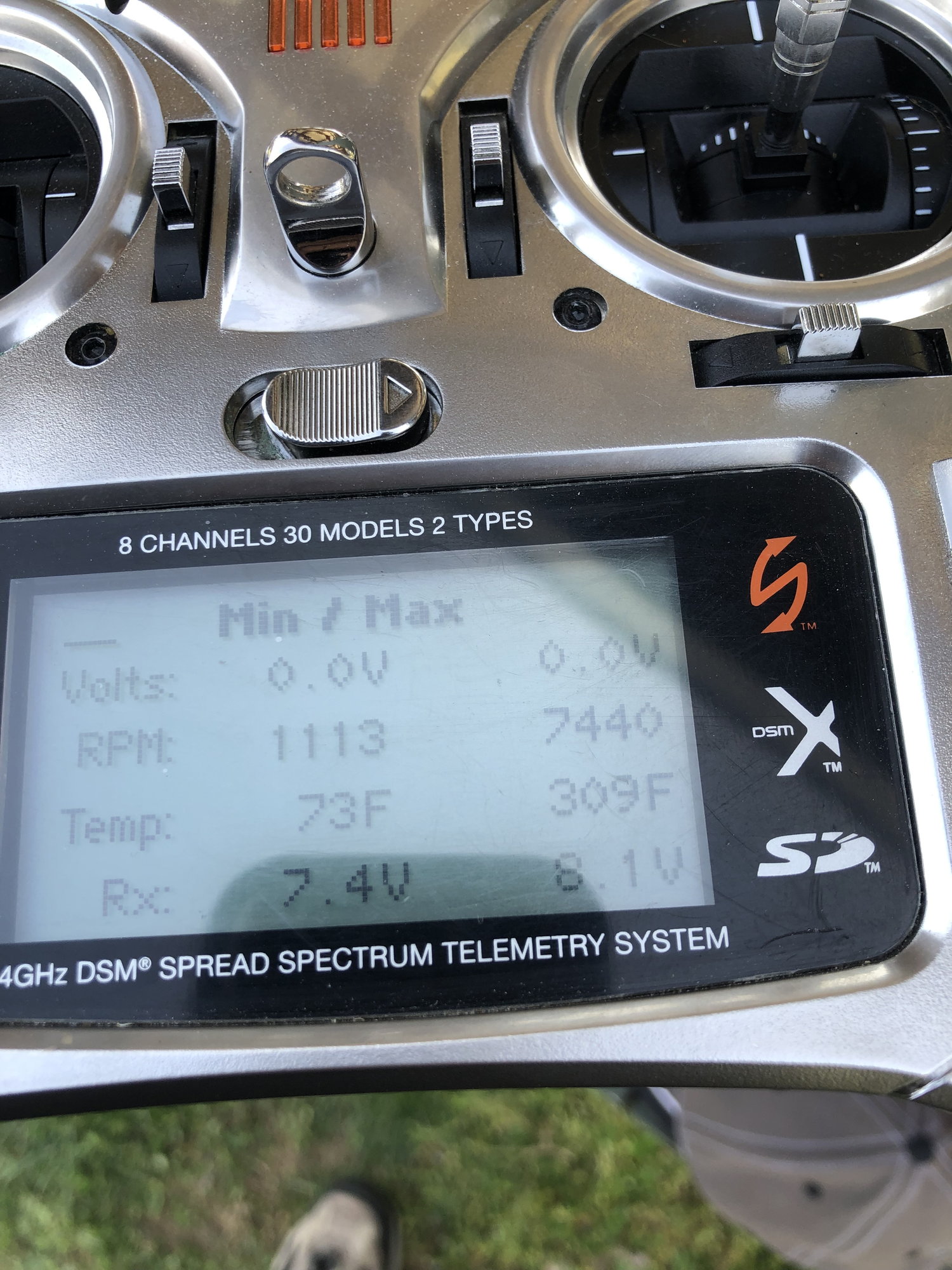

Two things i noticed in this flight. The plane was �slicker� today and I only needed 1/2 throttle. I was really trying to keep the rpm down and not over rev it. Every time I looked at my telemetry read out the temps were around 270 ish or cooler. The engine was on point today. So I will say that I did change my oil mix. I changed it from Stihl Ultra HP to Redline racing oil. I got it from my motorcycle dealer here in town. I didn�t retune the motor on the low side but I did richen up the high speed two clicks. Also I did have to lower my idle trim a good bit so it wouldn�t roll by itself. All in all I had a great day of flying the 60R3. Here is a pic of my telemetry after a flight. Again I was lowering throttle in dives and not going over 75% throttle.
03-23-2019, 06:38 PM
#2138
My Feedback: (2)
Octane reduces the ability of fuel to ignite. The higher the octane the more difficult it is for the fuel to ignite.
That's why high compression engines use higher octane fuels. They develop higher temps which would ignite lower octane fuels causing pre-detonation.
That's why high compression engines use higher octane fuels. They develop higher temps which would ignite lower octane fuels causing pre-detonation.
03-24-2019, 11:27 PM
#2139
Member
Not sure this engine has a high compression ratio. Has anyone ever measured it? Otherwise I would do it the next time this engine is on the bench. Remember that the valve blocked in open position did not touch the piston. So there is still some room...
But the issue of detonation is in my opinion rather related to the too important timing (up to 52 � before TDC on 1 cylinder) on this engine.
JM
But the issue of detonation is in my opinion rather related to the too important timing (up to 52 � before TDC on 1 cylinder) on this engine.
JM
03-25-2019, 03:57 AM
#2140
Senior Member
Not sure this engine has a high compression ratio. Has anyone ever measured it? Otherwise I would do it the next time this engine is on the bench. Remember that the valve blocked in open position did not touch the piston. So there is still some room...
But the issue of detonation is in my opinion rather related to the too important timing (up to 52 � before TDC on 1 cylinder) on this engine.
JM
But the issue of detonation is in my opinion rather related to the too important timing (up to 52 � before TDC on 1 cylinder) on this engine.
JM
And why are you citing #1 cylinder? Are you under the impression that the ignition timing varies significantly from cylinder to cylinder?
If you think there is a significant variance of timing between cylinders, where could you have possibly gotten that idea?
Last edited by SrTelemaster150; 03-25-2019 at 04:01 AM.
03-25-2019, 11:41 AM
#2142
Member
Why is your ignition timing so far advanced? I use 35 degrees BTDC with methanol. 52 degrees BTDC is at least 20 degree to far advanced for gasoline.
And why are you citing #1 cylinder? Are you under the impression that the ignition timing varies significantly from cylinder to cylinder?
If you think there is a significant variance of timing between cylinders, where could you have possibly gotten that idea?
And why are you citing #1 cylinder? Are you under the impression that the ignition timing varies significantly from cylinder to cylinder?
If you think there is a significant variance of timing between cylinders, where could you have possibly gotten that idea?
Note : I have modified my engine to have 30 degrees BTDC and it works really smoother.
JM
 03-26-2019, 06:28 AM
#2143
My Feedback: (48)
I've been using AVGAS (100LL) with Klotz @15:1 in my FG-60 since I got it thinking it'd be the best fuel to head off potential detonation and the fact it has no alcohol in it. I have been having some problems with carbon/sticking valves mostly on #3 cylinder which for some reason runs the hottest. I've changed over to a Morris ring/ 30 deg timing and it seems to run a little smoother/cooler. Haven't had a chance to fly it yet this year. Field is to soft/wet to fly heavy planes.
03-27-2019, 04:37 AM
#2144
Senior Member
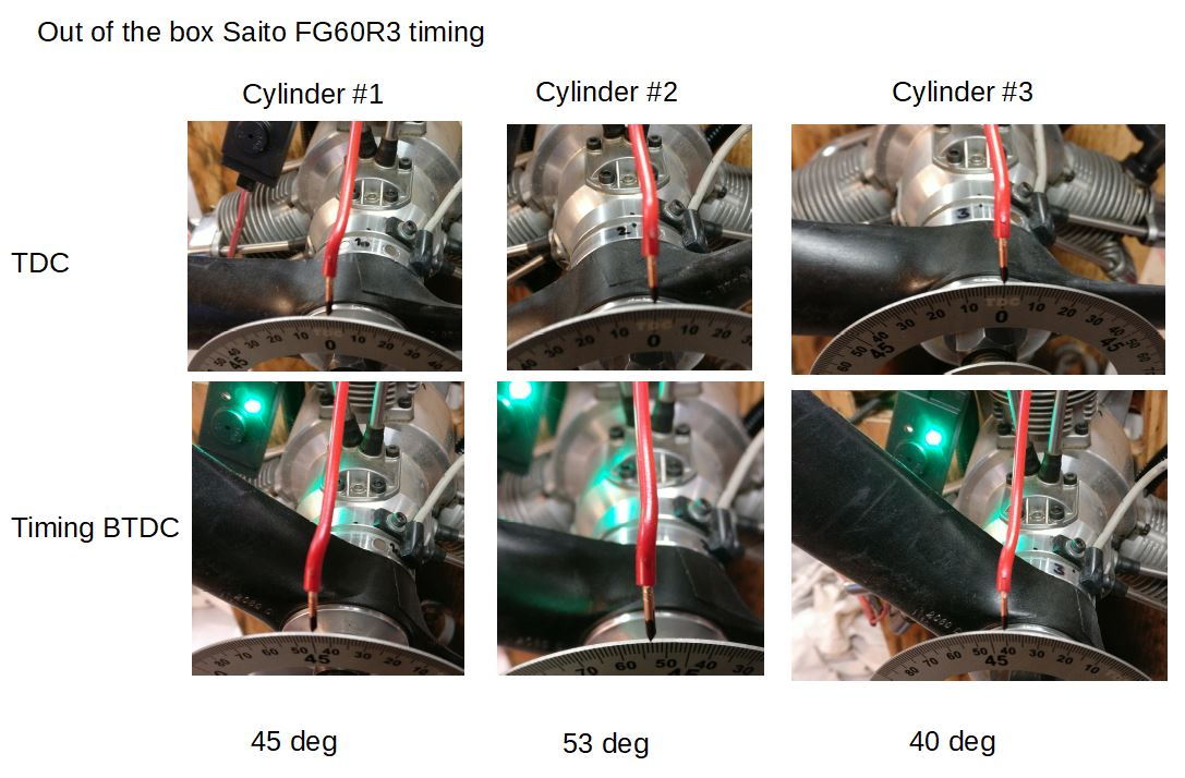
On this radial, cylinder #1 is working with a master rod and cylinder #2 and #3 are working with a slave rod. That is the reason, combined with the S magnets at 120� - 120� - 120� the ignition timing is NOT the same for each cylinder. Out of the box, ignition for cylinder #1 is 45� BTDC (even this value is too high for me), and 52� and 38� for the 2 others. Best result for me is 30� BTDC on EACH cylinder. And that is unfortunetly not the case with this saito product.
Note : I have modified my engine to have 30 degrees BTDC and it works really smoother.
JM
Note : I have modified my engine to have 30 degrees BTDC and it works really smoother.
JM
Unless the bores for the slave rod link pins are mislocated in the master rod, there will be no variance in the relationship of the TDC timing of the crankshaft for each individual cylinder. Nor will any degree value BTDC and ATDC be affected.
What changes is the relationship of the piston travel in the bore before and after TDC as well as the "dwell" at TDC. This can affect the effective ignition timing, but not in crankshaft degrees.
However, the relationship of #2 and #3 cylinder pistons in bore travel should be the same as long as the rotational direction of the crank remains the same.
03-27-2019, 10:12 PM
#2145
Member
 03-28-2019, 01:22 AM
#2146
Join Date: Jan 2007
Location: Dubai, UNITED ARAB EMIRATES
Posts: 500
Likes: 0
Received 2 Likes
on
2 Posts
Sr Telemaster, as Elmshoot says, go back and read a bit, there is a lot of information at hand. I think the MOST important fact, which JieM has shown in his pictures, is that the timing is way too advanced for a gasoline engine, by quite a way. The other thing is that measuring TDC on all cylinders, reveals that the TDC occurs at intervals of 126 between 1 & 2 cyl, 108 between 2 & 3 & 126 between 3 & 1, so there is a variance in the crank spacing between them, as a result of the main rod design.Its not misaligned, its designed like that.
That being the case, getting the timing to 30Deg BTDC on each jug, means having to space the magnets 126-108-126 on the circumference of the prop hub. If you have an FG engine, go ahead and measure it. If you have a reason to question our logic, we would accept your theory as we are all scratching our heads, here, and you are welcome to scratch along with us....or lead us in the path of a solution.
That being the case, getting the timing to 30Deg BTDC on each jug, means having to space the magnets 126-108-126 on the circumference of the prop hub. If you have an FG engine, go ahead and measure it. If you have a reason to question our logic, we would accept your theory as we are all scratching our heads, here, and you are welcome to scratch along with us....or lead us in the path of a solution.
03-28-2019, 04:03 AM
#2147
Senior Member
I reiterate; Unless the bores for the slave rod link pins are mislocated in the master rod, crankshaft degrees will not vary.
Will this affect detonation? Yes it will but it has nothing to do with crankshaft degrees.
Put a protractor over the master rod and measure the degrees of the link pin bore C/Ls. If they are all at 120 degrees then the timing of crankshaft degrees will not vary between cylinders.
It's geometry. If you are varying the timing to reflect 30 crankshaft degrees BTDC then your ignition is occurring at different distances on piston travel BTDC. Perhaps the variance is designed in to reflect piston travel instead of crankshaft degrees? I have an FA-450 master rod in my parts bin. I will measure the C/Ls of the link pin bores.
BTW I never use the light but just listen for the spark to set timing. It's quite reliable and simpler.
Last edited by SrTelemaster150; 03-28-2019 at 04:30 AM.
03-28-2019, 05:32 AM
#2148
Senior Member
Sr Telemaster, as Elmshoot says, go back and read a bit, there is a lot of information at hand. I think the MOST important fact, which JieM has shown in his pictures, is that the timing is way too advanced for a gasoline engine, by quite a way. The other thing is that measuring TDC on all cylinders, reveals that the TDC occurs at intervals of 126 between 1 & 2 cyl, 108 between 2 & 3 & 126 between 3 & 1, so there is a variance in the crank spacing between them, as a result of the main rod design.Its not misaligned, its designed like that.
That being the case, getting the timing to 30Deg BTDC on each jug, means having to space the magnets 126-108-126 on the circumference of the prop hub. If you have an FG engine, go ahead and measure it. If you have a reason to question our logic, we would accept your theory as we are all scratching our heads, here, and you are welcome to scratch along with us....or lead us in the path of a solution.
That being the case, getting the timing to 30Deg BTDC on each jug, means having to space the magnets 126-108-126 on the circumference of the prop hub. If you have an FG engine, go ahead and measure it. If you have a reason to question our logic, we would accept your theory as we are all scratching our heads, here, and you are welcome to scratch along with us....or lead us in the path of a solution.
A crude yet effective "gauge" could be fashioned form a round toothpick with the point trimmed back on one end. Doing your best to keep the toothpick angle consistent, measure the distance to the top of the #1 piston at 30* BTDC. Make a reference mark at the edge of the spark plug hole on the toothpick. Now rotate the crank 120*. Again insert the "gauge" until it contacts the piston crown. Make another reference mark like you did for #1 cylinder. Repeat for #3 cylinder.
Is the linear distance of the piston crown from TDC the same for all 3 cylinders? As a dynamic value, the position of the piston may be more important than the crankshaft degrees as the cylinder pressure will not be equal in all if the cylinders when the spark occurs of it is timed by crankshaft degrees.
Cylinder pressure is the main factor in detonation so perhaps some variance in ignition timing would be optimal for this engine given the variance in piston position relative to TDC in the bores of the 3 cylinders?
On glow ignition radials, it is cylinder pressure that determine ignition timing so it would be self correcting in a radial glow ignition engine. Perhaps the variance in ignition timing is designed in and merely pulling 15* out of a 120* crankshaft degree magnet spaced ring to reflect 30* BTDC timing for #1 cylinder would be correct.
Sitting here mulling over the variance from #2 & #3 cylinder timing has me wondering of a leading and trailing geometric effect of the linked rods compared to the master rod is a factor here.
BTW; I checked my FA-450R3 master rod and as close as I can tell, the link pin bores are at 120* spacing relative to the master rod bores.
03-28-2019, 06:10 AM
#2149
Senior Member
y
Sitting here mulling over the variance from #2 & #3 cylinder timing has me wondering of a leading and trailing geometric effect of the linked rods compared to the master rod is a factor here.
BTW; I checked my FA-450R3 master rod and as close as I can tell, the link pin bores are at 120* spacing relative to the master rod bores.
This will affect cylinder pressure @ 30 crankshaft * BTDC hence differing optimal ignition timing values for each cylinder to prevent detonation..
I did a crude drawing to wrap my head around it. I will do a better drawing to illustrate the difference.
Last edited by SrTelemaster150; 03-28-2019 at 06:20 AM.
03-28-2019, 06:52 AM
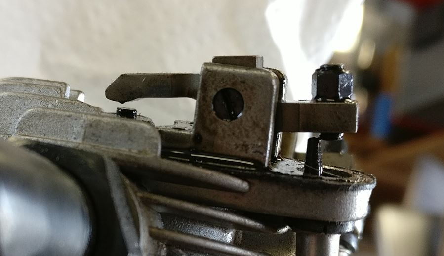
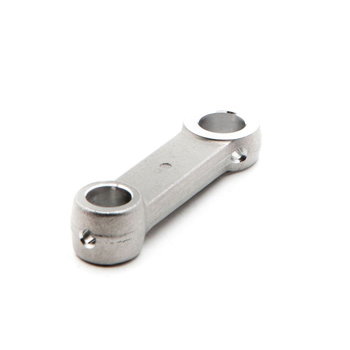
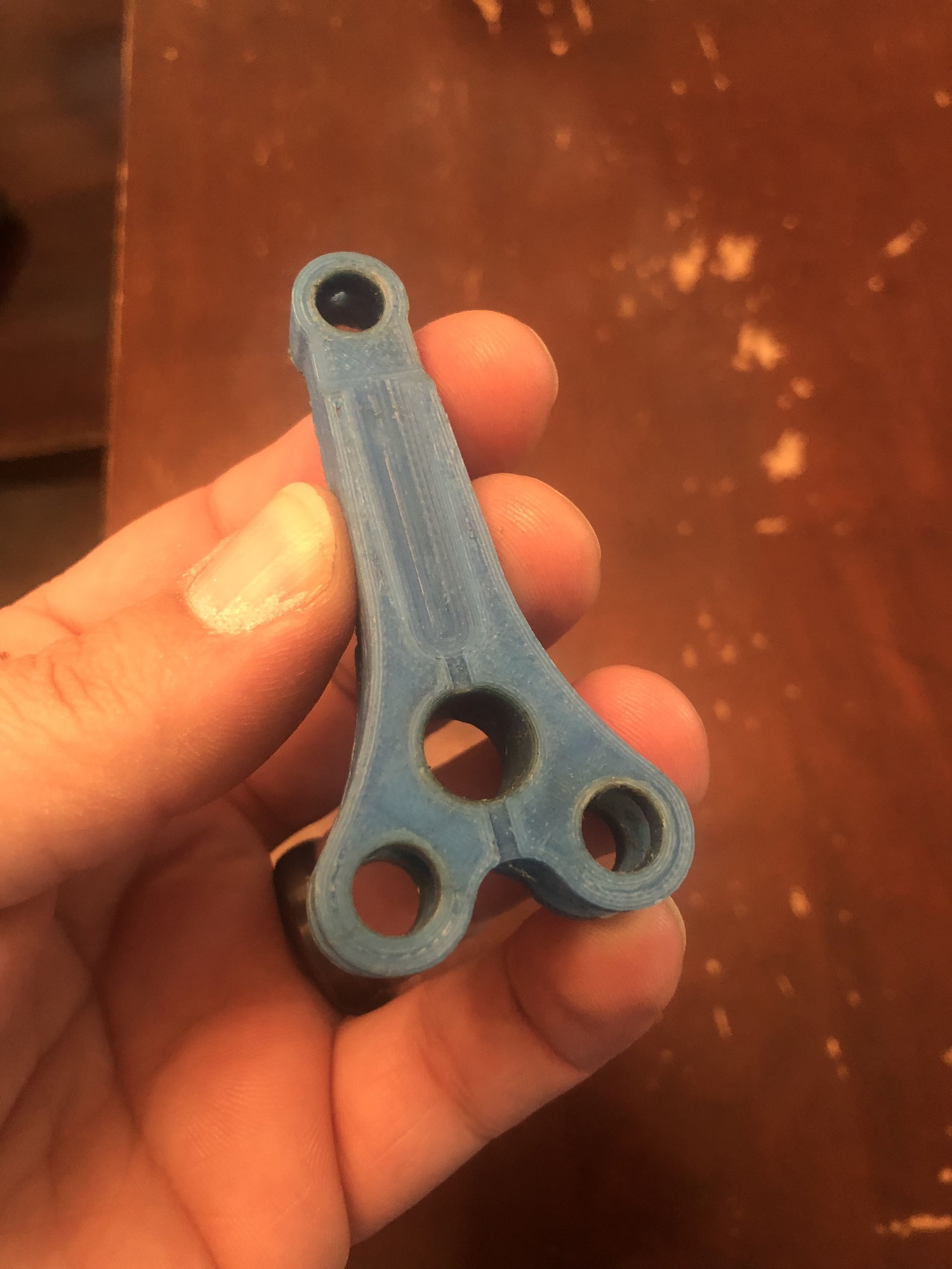
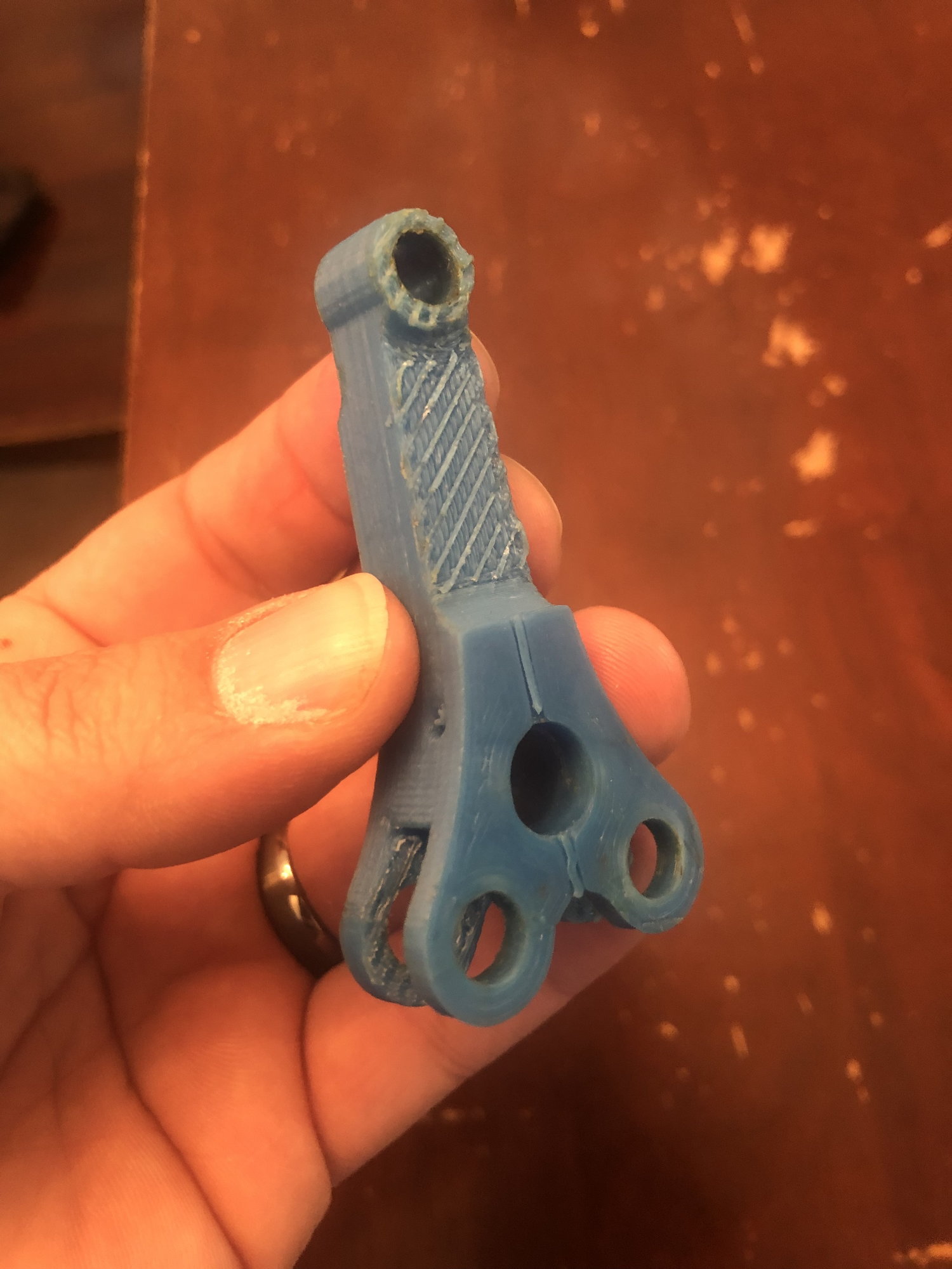
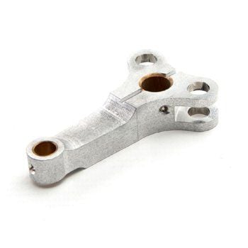
#2150
When I first cracked a cylinder head I looked up main causes for full size aircraft and it was something like the mixture was too lean and something about timing. (This was in 2016 I don�t fully remember) however since I had the engine apart I was looking at the relationship of the master rod and sister rods and the hole in the hole in the prop hub that has the pin to keep it in place. On No.1 the hole lines up with the hole in the cam cover and the piston is at the top of its stroke. However on 2 and 3 it has a little before and a little after. This confused me so after further investigation I thought the master rod was designed wrong. So with some time spent in AutoDesk Inventor and the use of a friends 3D printer I was able to make ( what I thought) a corrected master rod. See pics. I installed the part and yes it did correct the timing of the piston to be at top of stroke and the hole lined up with cam cover. But I brought the pistons to far down and would hit the crank and not allow it to rotate fully. That was as far as I went with the idea. I�ve included a pick of the master rod and you can see how I relocated the sister rod holes. Soon after I figured out that the timing of the magnets was not right but didn�t know how to fix it.